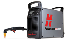
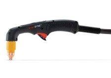
| Fault Code | Fault Icon | Fault LED | Description | Solutions |
|---|
| 0-11-0 |

|

Flashes Yellow
|
The remote control operating mode is incorrect or not permitted for the installed cartridge.
The permitted operating modes for cutting cartridges are 1 (Cut mode) and 2 (Expanded Metal mode). The permitted operating mode for a gouging cartridge is 3 (Gouge mode).
|
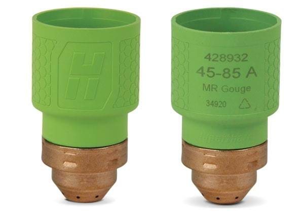
These fault codes do not stop the system from operating. Hypertherm recommends that you do the following. There is a problem with the remote control or the software interface to the system. The system cannot interpret the operating mode, output current, or gas pressure information coming
from the controller.
• Examine the programming code for incorrect process variables.
• Repair the controller.
|
| 0-11-1 |
 |

Flashes Yellow
|
The remote control output current (A) is incorrect or not permitted for the installed cartridge. The permitted values relate to the minimum and maximum output current (A) for the plasma power supply and the installed cartridge.
|
See above |
| 0-11-2 |
 |

Flashes Yellow
|
The remote control gas pressure is incorrect or not permitted. The permitted gas pressure relates to the selected process and operating mode, and to the installed torch, torch lead, and cartridge. |
See above |
| 0-12-1 |

|

Flashes Yellow
|
The gas pressure output is low.
|
These fault codes do not stop the system from operating. Hypertherm recommends that you do the following.
• For 0-12-1 faults, increase the inlet gas pressure from the gas supply source. For optimum system performance, make sure that the inlet gas pressure stays between 7.6 bar – 8.3 bar (110 psi – 120 psi) while gas is flowing. For minimum inlet pressure specifications, refer to page 57 of the operator manual.
• Never exceed the maximum gas pressure of 9.3 bar (135 psi). Refer to Inlet gas pressure requirements (while gas is flowing) on page 57 of the operator manual.
• Make sure that none of the gas lines are kinked or blocked.
• Do a gas test to see if the plasma power supply’s actual output gas pressure is lower than the set pressure by more than an acceptable quantity. Refer to Do a gas test on page 151 of the operator manual.
• Have a qualified service technician examine the solenoid valve inside the plasma power supply. Speak to your distributor or authorized repair facility (Welders Supply)
|
| 0-12-2 |
 |

Flashes Yellow
|
The gas pressure output is high.
|
See above |
| 0-12-3 |
 |

Flashes Yellow
|
The gas pressure output is not stable. |
See above |
| 0-13-0 |

|

Yellow

Flashes Green

Flashes Yellow
|
The alternating current (AC) input power is not stable.
|
This fault code does not stop the system from operating. In some conditions, the system can operate at a decreased capacity. Hypertherm recommends that you do the following.
• Do a cold restart.
• If applicable, disconnect the system from generator power. Refer to Troubleshoot power-related problems with generators on page 148 of the operator manual.
• If you continue to get this fault, have an electrical technician correct the power source. Refer to page 38 of the operator manual.
|
| 0-14-0 |

|

Yellow

Flashes Yellow
|
There is a problem with the cartridge installation.
|
This fault shows when you install a cartridge, and it cannot send data to the plasma power supply. This fault code stops the system from operating.
Do one of the following:
• Set the torch-lock switch to the yellow lock (X) position and then back to the green “ready to fire” (✓) position.
• Do a quick restart.
• Install the cartridge again. Electrical noise can cause a bad data connection. For example, high frequency electrical noise from TIG welders can cause interference. Keep electrical noise in the work area as low as possible. If you do not remove this fault code, the system automatically adjusts the following settings to prevent possible damage to the workpiece and cartridge:
• It sets the output current to 45 A.
• It sets the operating mode to Cut mode.
• It sets the output gas pressure to cut pressure.
If necessary, you can manually change these settings to cut without a data connection.
|
| 0-14-1 |
 |

Flashes Yellow
|
The cartridge is not recognized.
|
This fault shows when a cartridge cannot send data to the plasma power supply for some reason. This fault code does not stop the system from operating.
• When this fault occurs, you can continue to cut or gouge, but you must set the output current (A) and the operating mode manually. Also, the system cannot collect data about the Hypertherm cartridge.
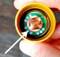
• Lightly blow air into the cartridge to remove all dust or other contamination. Install the cartridge again.
• Make sure that the green ring inside the cartridge is not broken.
|
| 0-19-9 |

|

Yellow

Flashes Yellow
|
The input power stopped. Or, power PCB hardware protection occurred for components in the plasma power supply.
|
This fault code stops the system from operating.
Do the following.
• This fault can be the result of electrical noise. Wait for the fault to go away, and continue to cut.
• If you use serial communications, this fault can occur temporarily on the CNC when you set the plasma power supply to
OFF (O). Wait for 1 minute for the fault to go away on its own.
• If this fault continues to occur, it can identify a possible hardware fault with an internal component., and you can see a A hardware fault shows as a 1-nn-n, 2-nn-n, or 3-nn-n fault code. A qualified service technician must repair the system. Speak to your distributor or authorized repair facility (Welders Supply).
|
| 0-20-0 |
 |

Yellow
|
The gas pressure is lower than the minimum pressure for the selected process, operating mode, torch, lead length, and Hypertherm cartridge type.
|
This fault code does not stop the system from operating. Do the following.
• Examine all the connections for the input gas supply. Make sure that there are no leaks or loose connections.
• Make sure that the incoming gas supply hose has an internal diameter of 10 mm (3/8 inch) or greater if the hose is less than 15 m (50 feet). For hoses that are 15 m – 30 m (50 feet – 100 feet), use an internal diameter of 13 mm (1/2 inch) or greater.
• Make sure that there is sufficient inlet gas pressure from the gas supply source. Refer to Inlet gas pressure requirements (while gas is flowing) on page 57 of the operator manual.
• Manually adjust the gas pressure on the plasma power supply. Refer to page 74 of the operator manual.
• Do a gas test to see if the plasma power supply’s actual output gas pressure is lower than the set pressure by more than an acceptable quantity. Refer to page 151 of the operator manual.
• If there is no apparent problem with the inlet gas supply, examine the air filter bowl and air filter element in the plasma power supply. Clean or replace as necessary. Refer to page 177 of the operator manual.
• If you continue to get this fault condition, have an authorized service technician examine the system. Speak to your distributor or authorized repair facility (Welders Supply).
|
| 0-21-0 |

|

Yellow

Yellow
|
The gas flow stopped during cutting (an excessive change to arc voltage occurred).
|
This fault code stops the system from operating. The fault code goes away the next time that you fire the torch unless there is a condition that prevents the torch from firing, such as a kink or blockage in the torch lead. Do the following.
• Make sure that the correct gas inlet pressure is available.
• Make sure that none of the gas lines are kinked or blocked.
• Make sure that the torch lead is not leaking. Also make sure that it is not kinked or twisted.
• Install a new Hypertherm cartridge.
• For mechanized applications, lock out the torch height control.
|
| 0-22-0 |
 |

Yellow

Yellow
|
There is no gas supply input.
|
This fault code stops the system from operating. The fault code goes away when you connect the gas supply to the plasma power supply unless there is a blockage in the gas line. Do the following.
• Make sure that the input gas supply is connected correctly to the plasma power supply.
• Examine all the connections for the input gas supply. Make sure that there are no blockages in the gas line. Make sure that there are no leaks or loose connections.
• Restart the plasma power supply.
|
| 0-30-0 |

|

Yellow

Yellow
|
There is a torch stuck open (TSO) condition.
The nozzle and electrode components inside the Hypertherm cartridge are not touching after a Start signal is received.
|
These fault codes stop the torch from firing a plasma arc. In some conditions, you can fire the torch again and continue to cut.
If the fault occurred when you first installed the cartridge and tried to fire the torch, do the following:
• If the Hypertherm cartridge became loose or was removed while the plasma power supply was ON and the torch-lock switch
was set to the green “ready to fire” position (✓), set the power switch on the plasma power supply to OFF (O), correct the problem, and set the power switch to ON (I) to remove the fault.
• Examine the Hypertherm cartridge. Make sure that it is not worn or damaged. Refer to Signs that a cartridge is near end-of-life on page 107 and Cartridge maintenance on page 176 of the operator manual.
• Hand torch: Move the torch-lock switch to the yellow lock (X) position, then move the torch-lock switch to the green “ready to fire” (✓) position. Fire the torch 1 time to get the warning puffs of air. This can clean away unwanted material that has collected around the tip of the cartridge.
• Remove the cartridge and carefully shake it to remove unwanted material that has collected inside the cartridge. This material can cause 0-30-0 faults to occur. A higher rate of 0-30-0 faults is typical as a cartridge gets near end-of-life.
• Install a new Hypertherm cartridge.
If the fault occurred during postflow or during a cut, do the following:
• Examine the gas line. Refer to Examine the gas pressure on page 126 and Examine the gas quality on page 127 of the operator manual.
• If the Hypertherm cartridge is in good condition and is installed correctly, the torch has possible damage. Speak to your
distributor or authorized repair facility.Examine the torch for damage and for conditions that can prevent correct gas
flow. Refer to Troubleshoot 0-30-0 fault codes that occur during postflow on page 149 of the operator manual.
|
| 0-30-1 |
 |

Yellow

Yellow
|
There is a torch stuck closed (TSC) condition.
The nozzle and electrode components inside the Hypertherm cartridge will not disconnect from each other after a Start signal is received.
|
See above |
| 0-32-0 |

|

Yellow

Red
|
The system sensed that the cartridge in use is at end-of-life.
|
This fault code stops the system from operating. Install a new cartridge to remove the fault condition.
• If you restart the plasma power supply and try to use the same cartridge, the 0-32-1 fault code shows to remind you that the cartridge is at end-of-life. Hypertherm strongly recommends that you install a new cartridge. Refer to When to replace
the cartridge (fault code 0-32-n) on page 80 of the operator manual.
|
| 0-32-1 |
 |

Yellow

Flashes Yellow
|
A cartridge is installed that had the 0-32-0 fault before and is at end-of-life.
|
This fault code does not stop the system from operating.
• The 0-32-1 fault code reminds you that the cartridge is at end-of-life. Hypertherm strongly recommends that you install a
new cartridge. Refer to When to replace the cartridge (fault code 0-32-n) on page 80 of the operator manual.
|
| 0-40-0 |

|

Yellow

Yellow
|
The boost power-factor correction insulated-gate bipolar-transistor (PFC IGBT) is too cold.
This is applicable to CSA and to Powermax105 SYNC 230 V – 400 V CE models only.
|
These fault codes stop the system from operating. Do the following. You can continue to use the system when its internal temperature is no longer too hot or too cold. Hypertherm recommends that you operate the system only in external temperatures between -10°C to 40°C (14°F to 104°F).
• The system is possibly overheated. Keep the plasma power supply ON to let the fan decrease the temperature of the internal components. Refer to Prevent overheating on page 81 of the operator manual.
• Make sure that there is sufficient air flow around the plasma power supply.
• Make sure that the plasma power supply cover is installed with the louvers in front of the fan.
• The system is possibly too cold to operate.
• If the internal temperature of the plasma power supply gets near -30°C (-22°F), move the system to a warmer location.
|
| 0-40-1 |
 |

Yellow

Yellow
|
The boost PFC IGBT is too hot.
This is applicable to CSA and to Powermax105 SYNC 230 V – 400 V CE models only.
|
See above |
| 0-40-2 |

|

Yellow

Yellow
|
The inverter IGBT is too cold.
|
See above
|
| 0-40-3 |
 |

Yellow

Yellow
|
The inverter IGBT is too hot.
|
See above |
| 0-50-0 |

|

Yellow

Yellow
|
The cartridge is off, the torch was disconnected, or the torch was in the yellow lock (X) position during a restart.
|
This fault code stops the system from operating. Do the following.
• This fault code shows when you do a restart while the torch-lock switch is in the yellow lock (X) position. Move the torch-lock switch to the green “ready to fire” (✓) position to continue. Refer to fault code 0-50-1 below.
• This fault code also shows if the torch is disconnected when you set the plasma power supply to ON (I). Connect the torch
to the plasma power supply. Do a quick restart.
• This fault code also shows when a cartridge is not installed correctly. Remove the Hypertherm cartridge and install it correctly.
• Machine torch: This fault code shows when you remove the cartridge without first setting the power switch to OFF (O) or moving the torch-lock switch to the yellow lock (X) position. Lock and unlock the torch, or do a quick restart.
• Mini machine torch: This fault code can show if you change the cartridge while the power switch on the plasma power supply is set to ON (I). Do a quick restart.
• If the Hypertherm cartridge is in good condition and is installed correctly, the torch has possible damage. Speak to your distributor or authorized repair facility.
|
| 0-50-1 |
 |

Yellow

Yellow
|
The torch-lock switch is set to the yellow lock (X) position.
|
This fault code stops the system from operating. Do the following. A restart is not necessary.
• Hand torch: Move the torch-lock switch to the green “ready to fire” (✓) position. Fire the torch 1 time to get the warning puffs of air. Fire the torch again to get a plasma arc. Refer to page 68 of the operator manual.
• Machine torch: Move the torch-lock switch to the green “ready to fire” (✓) position. Fire the torch to get a plasma arc.
• Mini machine torch: This fault code is not applicable to the mini machine torch.
|
| 0-50-2 |
none
|

Yellow
|
The torch-lock switch is set to the green “ready to fire” (✓) position, but the torch is not prepared to fire.
|
This fault code identifies a condition in which an additional step is necessary for hand torches before the hand torch will fire a plasma arc.
• When you move the torch-lock switch to the green “ready to fire” (✓) position, the fault code changes from 0-50-1 to 0-50-2, and the  icon goes off. icon goes off.
• Hand torch: Fire the torch 1 time to get the warning puffs of air. The 0-50-2 fault code goes off, and the LED on the hand torch changes from yellow to green. The torch is now prepared to fire a plasma arc.
• Machine torch: The 0-50-2 fault code shows for approximately 1 second and then goes off. Fire the torch to get a plasma arc. There are no warning puffs of air. If the 0-50-2 fault code does not go off, send a STOP signal from the CNC to remove the fault.
• Mini machine torch: This fault code is not applicable to the mini machine torch.
|
| 0-50-3 |
none |

Yellow
|
The torch-lock switch is set to the yellow lock (X) position.
|
This fault code flashes quickly while the system reads configuration data from the cartridge. Wait for the fault code to go away on its own.
• The system will not cut until the fault code goes away.
• This fault code can show for up to 6 seconds if electrical noise causes interference with the data connection.
• If the system cannot read the data from the cartridge, a different fault code will show.
• Hand torch: The usual behavior is to see a 0-50-2 fault code after 0-50-3 goes away. Fire the torch 1 time to get the warning puffs of air. The 0-50-2 fault code goes away. The torch is now prepared to fire a plasma arc.
|
| 0-51-0 |

|

Yellow

Yellow
|
The plasma power supply was receiving a signal to start cutting at the same time that the power switch was set to ON (I). With a machine torch, this condition is sometimes referred to as a “stuck start.”
|
This fault code stops the system from operating. Do the following. A quick restart is necessary.
• Hand torch: The torch trigger was being held in the “fire” position when the power switch on the plasma power supply was set to ON (I). Release the trigger and do a quick restart of the plasma power supply.
• Machine torch: The plasma power supply was receiving a Start signal when the power switch was set to ON (I). Set the Start signal to off, and do a quick restart of the plasma power supply.
|
| 0-52-0 |
 |

Yellow

Yellow
|
The torch is not connected.
|
This fault code stops the system from operating. Do the following. A quick restart is necessary.
• Make sure that the torch lead is correctly connected to the FastConnect receptacle on the front of the plasma power supply. Do a quick restart.
• If you disconnect the torch while the plasma power supply is set to ON (I), you get the 0-52-0 fault code.
• If you disconnect the torch while the plasma power supply is set to OFF (O), you get the 0-50-0 fault code the next time you set the plasma power supply to ON (I).
|
| 0-60-0 |

|

Yellow

Yellow
|
An AC input voltage phase loss occurred. This is applicable only to CE
models and to Powermax105 SYNC CSA models.
|
This fault code stops the system from operating. Do the following. A cold restart is necessary.
• Have an electrical technician examine all input phases and fuses/breakers for correct voltage at the power source and at the plasma power supply.
• If applicable, disconnect the system from generator power, or set the generator mode feature to on. Refer to Troubleshoot
power-related problems with generators on page 148 of the operator manual.
|
| 0-60-1 |
 |

Yellow

Yellow
|
An AC input voltage is too low.
|
This fault code stops the system from operating. Do the following. A cold restart is necessary.
• The input line voltage is too low (more than 15% below the rated voltage). Have an electrical technician examine the line and increase the voltage. Refer to page 22 and page 40 of the operator manual.
• If applicable, disconnect the system from generator power, or set the generator mode feature to on. Refer to Troubleshoot power-related problems with generators on page 148 of the operator manual.
|
| 0-60-2 |

|

Yellow

Yellow
|
An AC input voltage is too high.
|
This fault code stops the system from operating. Do the following. A cold restart is necessary.
• The input line voltage is too high (more than 10% above the rated voltage). Have an electrical technician examine the line and decrease the voltage. Refer to page 22 and page 40 of the operator manual.
• If applicable, disconnect the system from generator power, or set the generator mode feature to on. Refer to Troubleshoot power-related problems with generators on page 148 of the operator manual.
|
| 0-61-0 |
 |

Yellow

Yellow
|
An AC input is not stable. Shut down the system.
|
This fault code stops the system from operating. Do the following. A cold restart is necessary.
• The current from the incoming power line is unstable. Stop power to the system and correct the line resonance problem before continuing.
• If possible, connect the system to a different AC power source.
• Make sure that the plasma power supply is not being used on a phase converter.
• If applicable, disconnect the system from generator power, or set the generator mode feature to on. Refer to Troubleshoot power-related problems with generators on page 148 of the operator manual.
|
| 0-98-0 |
 |

Yellow

Yellow
|
An internal communication failure occurred between the LCD/control PCB and the DSP PCB.
|
This fault code does not stop the system from operating. The system can continue to cut, but Hypertherm recommends that you find the cause of the problem first because the controls on the front panel are not available. Do the following:
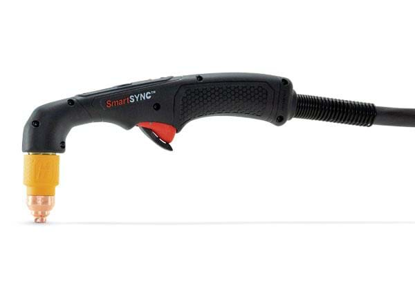
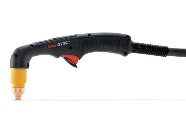
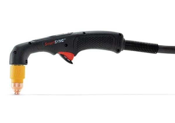
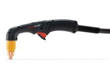
• Set the power switch on the plasma power supply to OFF (O). Wait until all the amperage LEDs on the SmartSYNC hand torch go off. (Or, wait approximately 1 minute.) Set the power switch to ON (I).
If the problem continues, a qualified service technician must open the plasma power supply and examine the ribbon cable between the LCD/control PCB and the DSP PCB.
|
| 0-98-1 |

|

Yellow
|
An RF communication failure occurred between the cartridge and the torch.
|
This fault code does not stop the system from operating. Hypertherm recommends that you do the following.
When this fault occurs, the Hypertherm cartridge is not sending data to the system, so the system cannot collect data about the cartridge. The problem can be with the Hypertherm cartridge or with the SmartSYNC torch.
You can continue to cut or gouge, but you must set the output current (A) and the operating mode manually.
Cartridge:
• Make sure that the Hypertherm cartridge is installed correctly.
• Make sure that the green ring inside the cartridge is not broken.
• If you have a Hypertherm cartridge reader (528083), do a test to identify if the reader can pull data from the cartridge.
• Install a new Hypertherm cartridge.

Torch:
• If a new Hypertherm cartridge does not remove the fault condition, a component in the SmartSYNC torch has possible damage. A qualified service technician must examine the torch. Speak to your distributor or authorized repair facility.
|
| 0-98-2 |
 |

Flashes Yellow
|
A communication failure occurred between the torch and the plasma power supply.
|
This fault code does not stop the system from operating. Hypertherm recommends that you do the following.
When this fault occurs, the SmartSYNC torch is not sending data to the plasma power supply, so the system cannot collect data about the Hypertherm cartridge. The problem can be with the torch or with the plasma power supply. A qualified service technician must identify the source of the fault and repair the component that is damaged. Speak to your distributor or authorized repair facility.
You can continue to cut or gouge, but you must set the output current (A) and the operating mode manually.
|
|
1-nn-n
2-nn-n
3-nn-n
|
 |

Yellow

Red
|
A major fault occurred.
Fault codes in the 1-nn-n, 2-nn-n, and 3-nn-n formats identify possible damage to components inside the plasma power supply.
These faults show on the Power Supply Log screen.
|
These fault codes stop the system from operating. Do the following.
• Do a cold restart. In some conditions, a restart can remove the fault condition.
• If restarting the plasma power supply does not remove the fault condition, a qualified service technician must repair the system. Speak to your distributor or authorized repair facility.
|








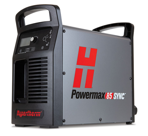


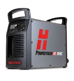
 1" Cut Capacity
 Multiphase
 Multi-Voltage
 Power Supply Only
 3-Year Power Warranty
 First Time Student Rebate

 System Information and Applications